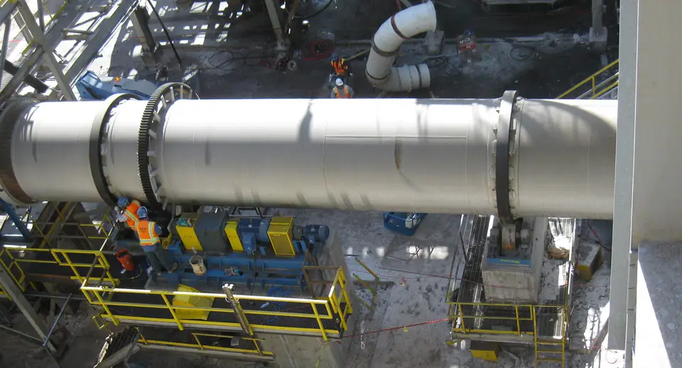
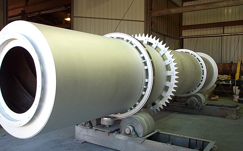
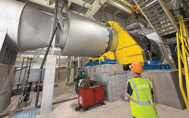
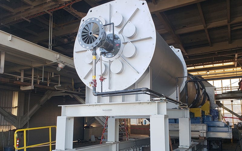
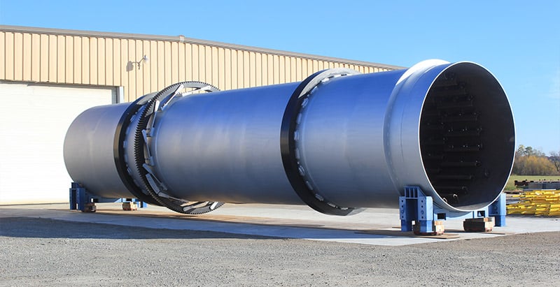
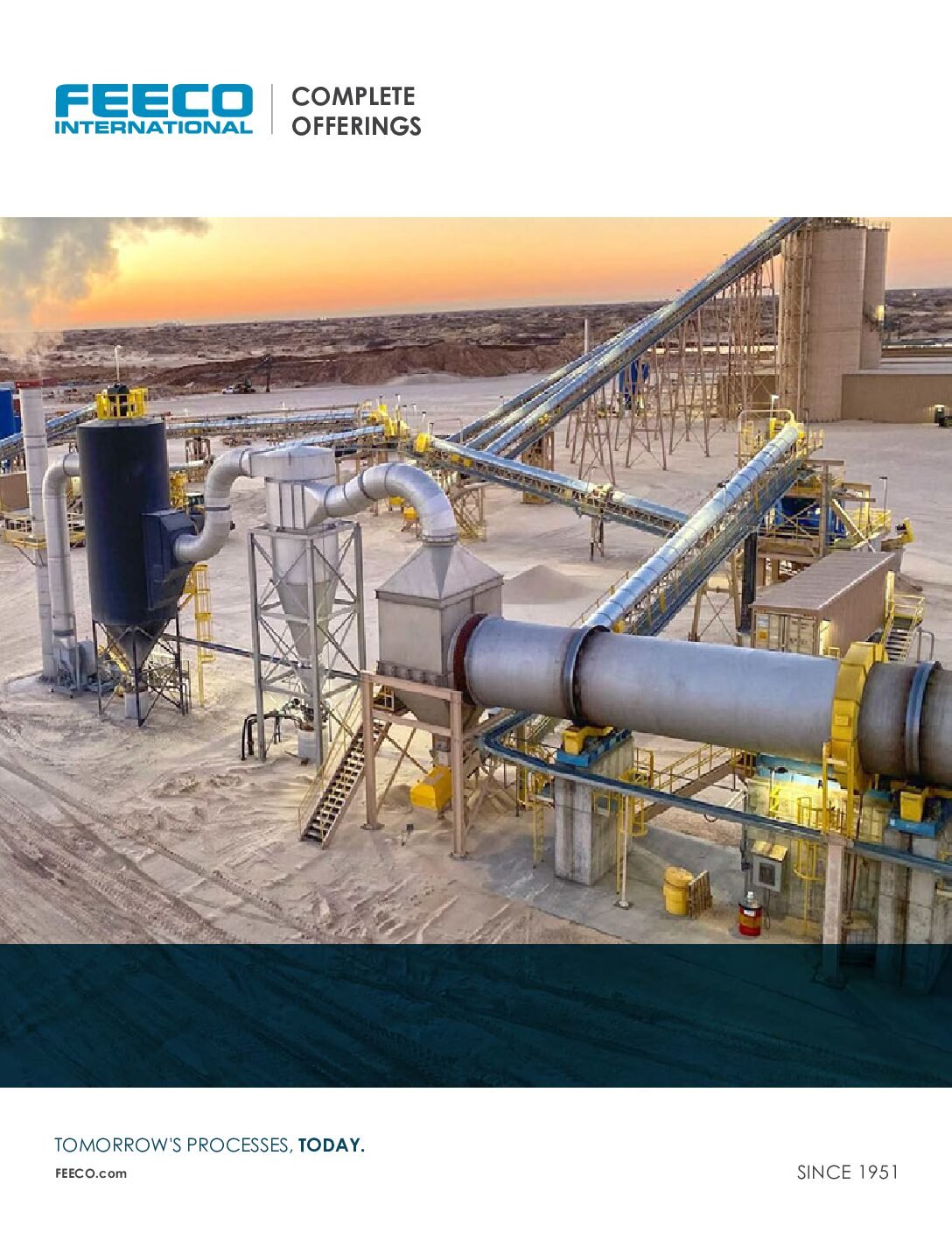
DIRECT ROTARY DRUM DRYERS
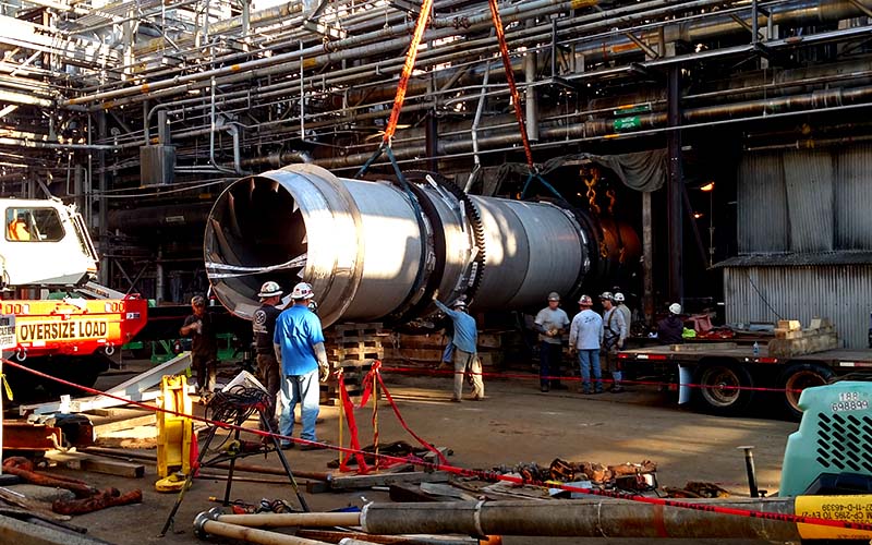
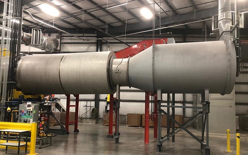
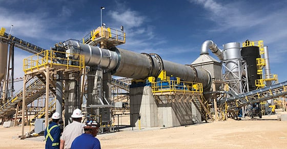
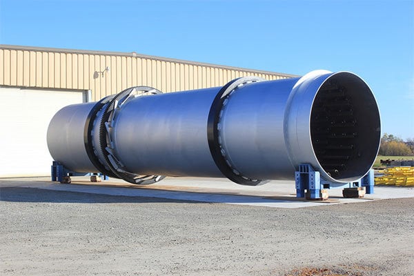
All FEECO rotary dryers are custom designed to suit the process and material goals of the project at hand. Whether you require low- or high-inlet temperatures, short or long residence times, counter-current or co-current flow, our design team can engineer and fabricate a rotary dryer uniquely suited to your application.
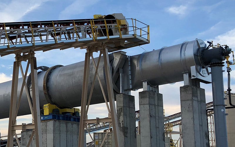
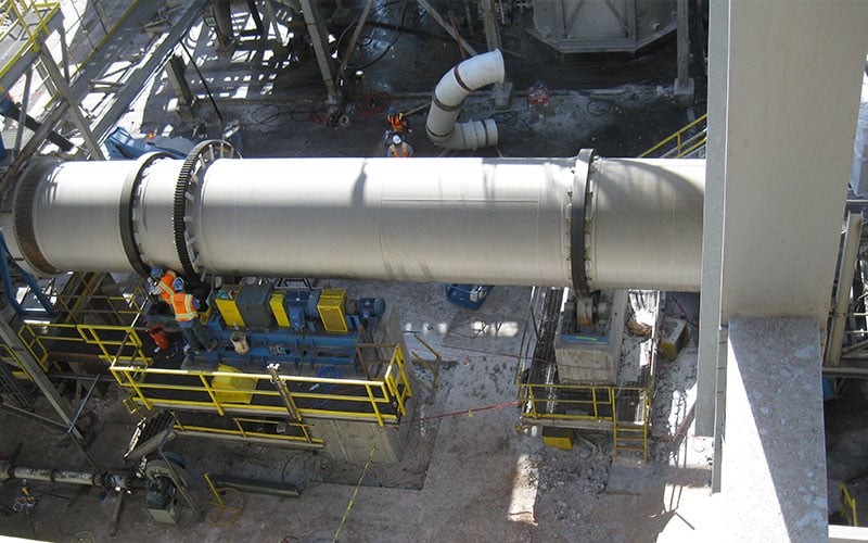
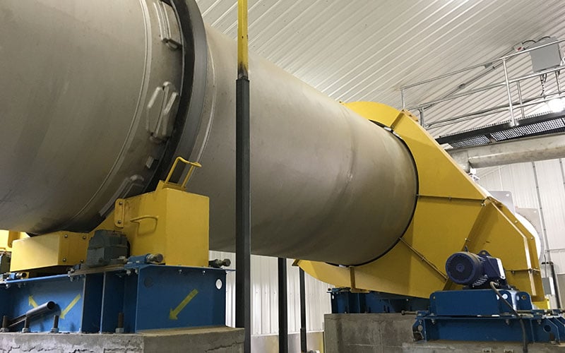
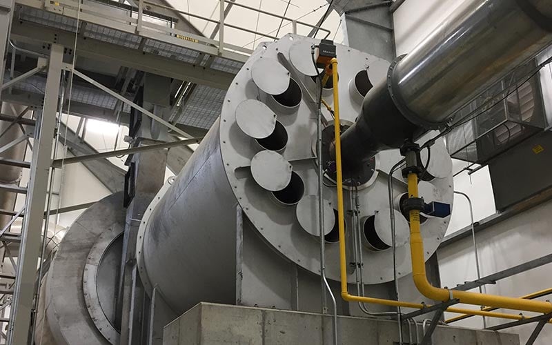
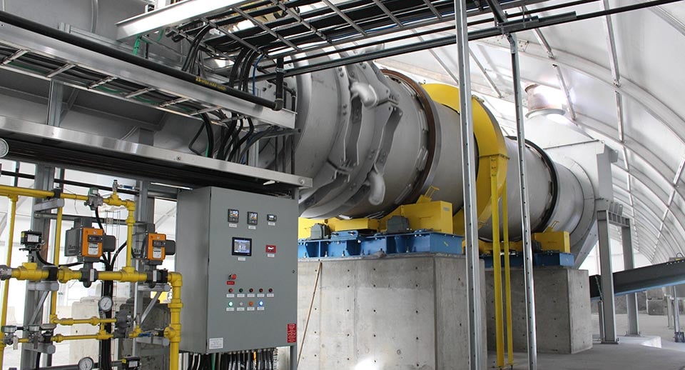
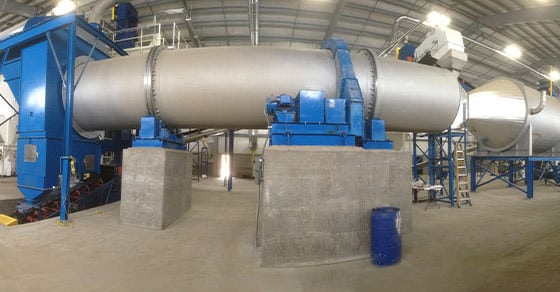
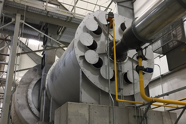
Rotary dryers are often chosen for their robust processing capabilities, high throughput, and tolerance to variation in feedstock characteristics. They work by tumbling material in a rotating drum in the presence of a drying air. They can also be indirectly heated to avoid direct contact between the material and processing medium.
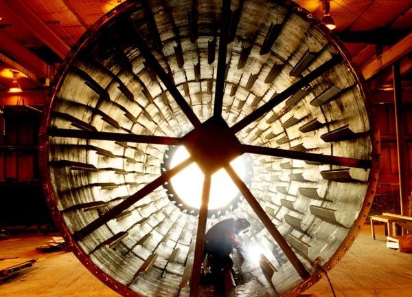
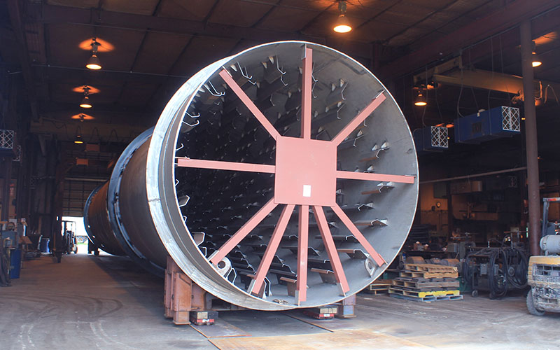
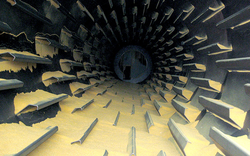
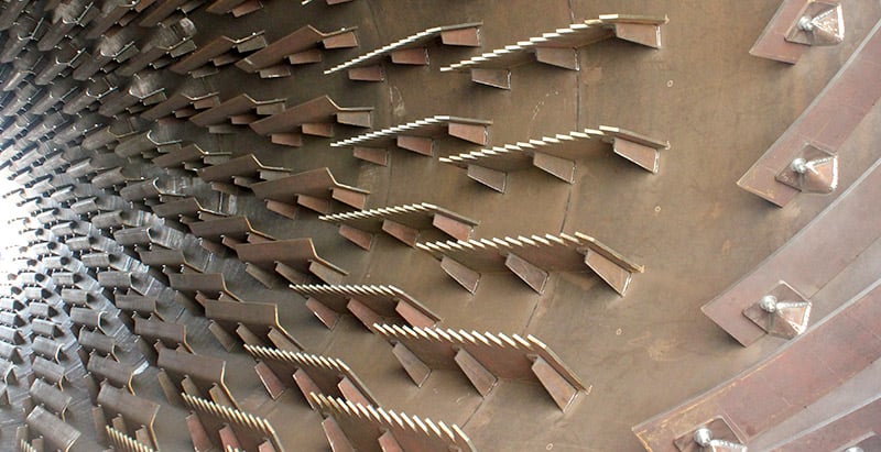
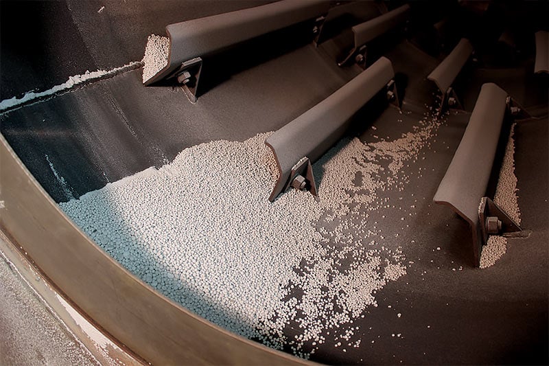
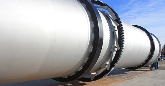
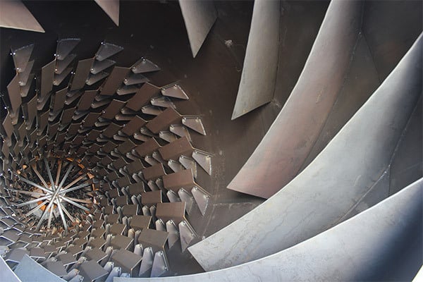
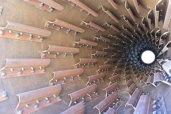
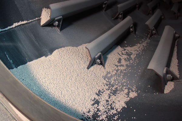
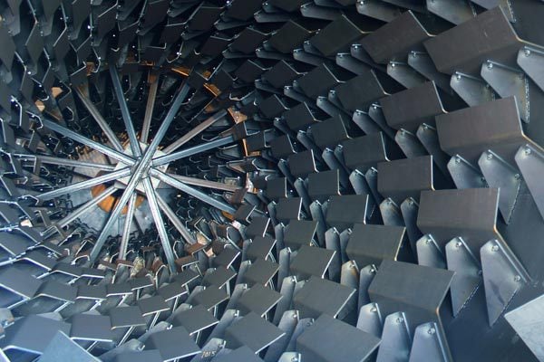
The drum is positioned at a slight horizontal slope to allow gravity to assist in moving material through the drum. As the drum rotates, lifting flights pick up the material and drop it through the air stream in order to maximize heat transfer efficiency (applicable to direct-fired dryers only). When working with agglomerates, the tumbling action imparted by the dryer offers the added benefit of further rounding and polishing the granules.
FEATURES
- Diameter: 3′ – 15′ (1 – 4.6m)
- Capacity: 1 TPH – 200 TPH (1 MTPH – 181 MTPH+)
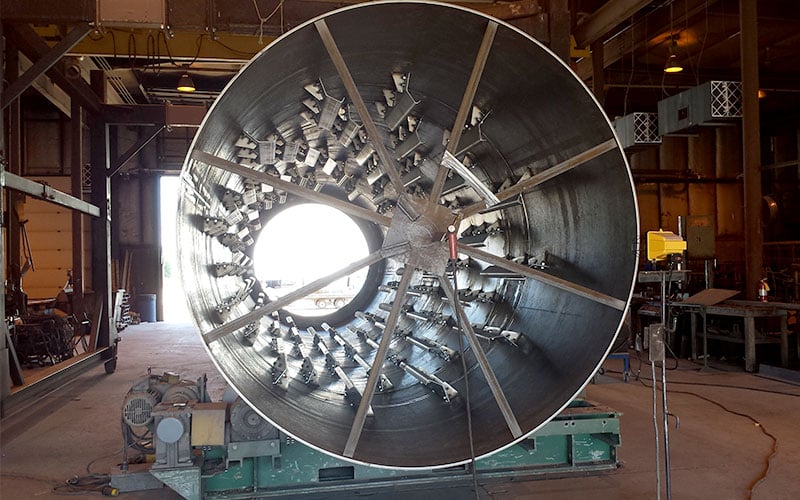
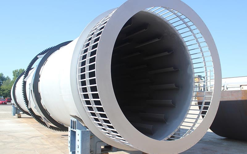
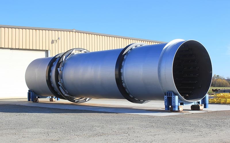
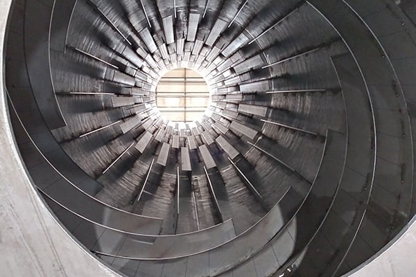
- Specially designed lifting flights to maximize heat transfer between the material and hot gas stream
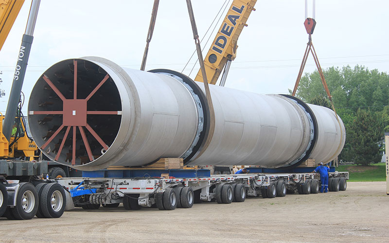
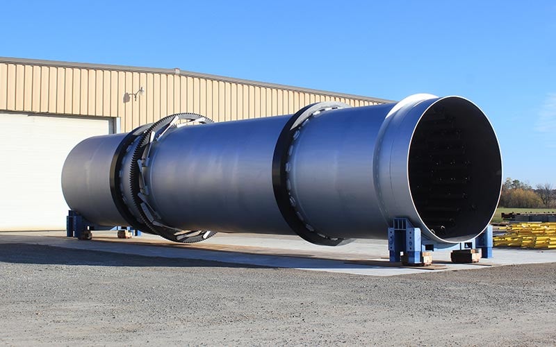
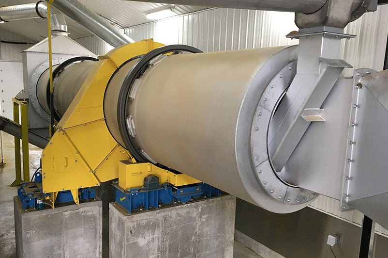
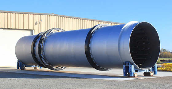
- Heavy-duty design and construction for many years of service
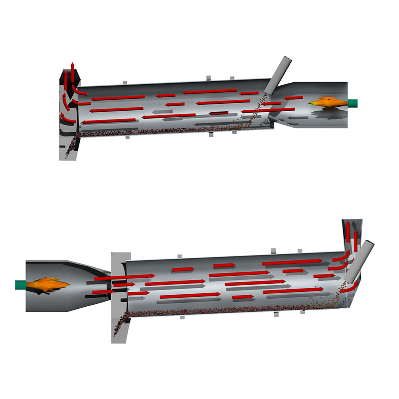
- Co-current (parallel flow) or counter-current configuration
- Process and mechanical warranties
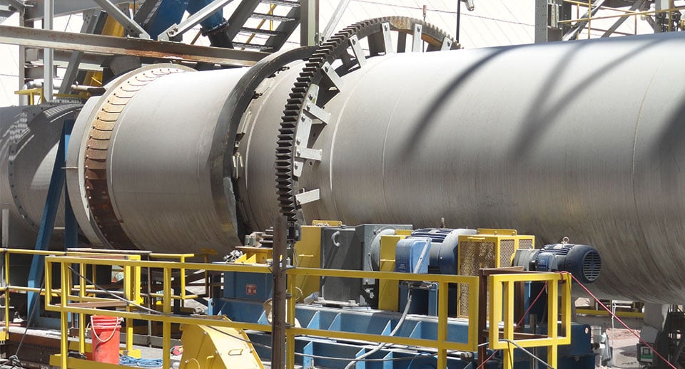
- Various drive assemblies available
Rotary Dryer Sizing
The chart below illustrates common rotary dryer data points. Please note that all FEECO equipment
is custom engineered around the project at hand, and this data is only a general representation.
| STANDARD | METRIC | ||||||||
| Diameter (ft.) | Length (ft.) | Capacity (STPH)* | HP | Diameter (m) | Length (m) | Capacity (MTPH)* | k5.5W | Heat Source | Drive Sprocket or Gear |
| 3′ | 20-30′ | 8 | 7.5 | .9 | 6-9 | 7 | 5.5 | Gas or Oil | Sprocket |
| 4′ | 20-30′ | 20 | 10-15 | 1.2 | 6-9 | 18 | 7.5-11 | Gas or Oil | Sprocket |
| 5′ | 20-40′ | 30 | 15-25 | 1.5 | 6-12 | 27 | 11.0-18.5 | Gas or Oil | Sprocket |
| 6′ | 30-50′ | 45 | 25-40 | 1.8 | 9-15 | 41 | 18.5-30 | Gas or Oil | Sprocket |
| 7′ | 40-60′ | 60 | 50-60 | 2.1 | 12-18 | 55 | 37-45 | Gas or Oil | Sprocket |
| 8′ | 50-70′ | 80 | 75-125 | 2.4 | 15-21 | 73 | 55-90 | Gas or Oil | Sprocket |
| 9′ | 50-80′ | 100 | 100-125 | 2.7 | 15-24 | 91 | 75-90 | Gas or Oil | Sprocket |
| 10′ | 50-80′ | 125 | 100-200 | 3.0 | 12-24 | 114 | 75-150 | Gas or Oil | Gear |
| 11′ | 60-90′ | 150 | 150-250 | 3.4 | 18-27 | 136 | 110-150 | Gas or Oil | Gear |
| 12′ | 60-90′ | 180 | 200-300 | 3.6 | 18-27 | 164 | 150-220 | Gas or Oil | Gear |
| 13′ | 70-100′ | 210 | 250-350 | 4.0 | 21-31 | 191 | 185-260 | Gas or Oil | Gear |
| 14′ | 70-100′ | 250 | 300-400 | 4.3 | 21-31 | 227 | 225-300 | Gas or Oil | Gear |
*Varies with materials to be dried. Capacity based on 60#/Cu. Ft. granular fertilizer materials having up to 10% moisture removal.
Optional Components
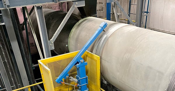
- Knocking Systems
- Trommel Screen
- Liners
- Leaf Seals
- Graphite Seals
- Machined Bases
- Screw Conveyor Feeder
- Automatic Gear Lubrication System
- Exhaust Handling Equipment
- Ductwork
Material Options
- Carbon Steel
- Stainless Steel
- Specialty Alloys
- Explosion Bonded
- AR Steel
Accommodates Various Fuel Types
- Fuel Oil
- Natural Gas/Propane
- Waste Heat
- Biogas
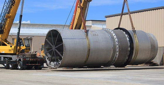
We can offer cost-competitive designs for pilot-scale units that process as little as one ton per hour to heavy-duty units in excess of 17 foot in diameter that process hundreds of tons per hour.
FEECO is capable of meeting the requirements necessary for CE marking equipment.
All FEECO equipment and process systems can be outfitted with the latest in automation controls from Rockwell Automation. The unique combination of proprietary Rockwell Automation controls and software, combined with our extensive experience in process design and enhancements with hundreds of materials provides an unparalleled experience for customers seeking innovative process solutions and equipment. Learn more >>
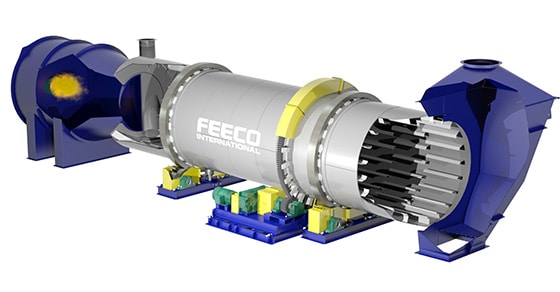
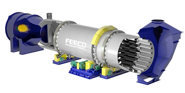
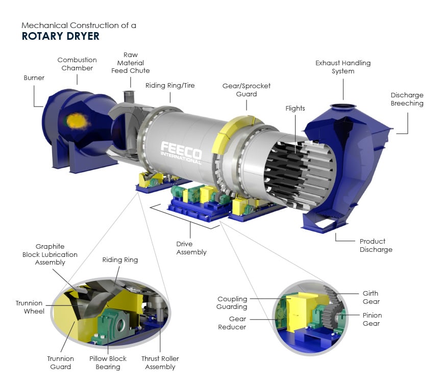
DIRECT ROTARY DRUM DRYER COMPONENTS AND PARTS
The image below shows the standard components of a direct-fired rotary dryer. Click image to view larger.
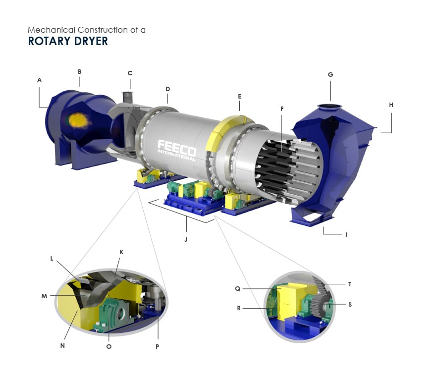
A – Burner
B – Combustion Chamber
C – Raw Material Feed Chute
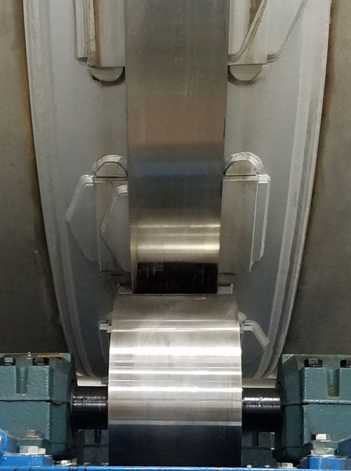
D – Riding Ring/Tire
E – Gear/Sprocket Guard
F – Flights
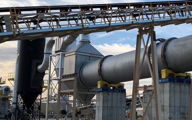
G – Exhaust Handling System
H – Discharge Breeching
I – Product Discharge
J – Drive Assembly
K – Drum Shell Riding Ring
L – Graphite Block Lubrication Assembly
M – Trunnion Wheel
N – Trunnion Guard
O – Pillow Block Bearing
P – Thrust Roller Assembly
Q – Coupling Guard
R – Gear Reducer
S – Pinion Gear
T – Girth Gear
For more detailed component descriptions, see the Rotary Dryer Parts and Components Glossary.
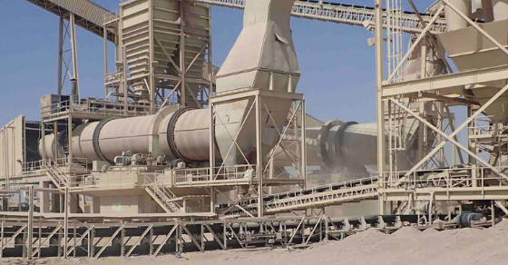
APPLICATIONS & MATERIALS
Rotary dryers are known as the workhorse of industrial dryers. They are able to process a wide variety of materials, and can lend a hand in nearly any industry requiring industrial drying solutions. Some of the most common industries and materials in which FEECO rotary dryers are employed include:
- Aggregates
- Agricultural By-Products
- Animal Feeds
- Biosolids (Municipal Sewage Waste & Sludge)
- Catalysts
- Fertilizers
- Fly Ash
- Gypsum
- Inorganic Chemicals
- Limestone
- Manure
- Metal Chips & Shavings
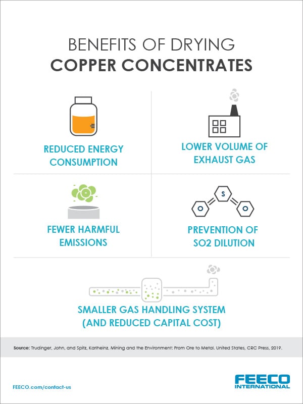
- Mining Ores & Concentrates
- Organic Chemicals
- Paper Sludge
- Plastic Pellets & Grains
- Potash
- Reclaimed Dust
- Roofing Granules
- Rubber Pellets
- Salts & Sugars
- Sand
- Steel Mill Waste Sludges
- Urea Prills & Crystals
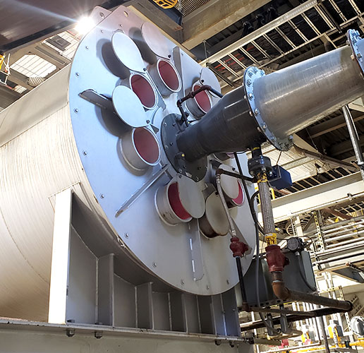
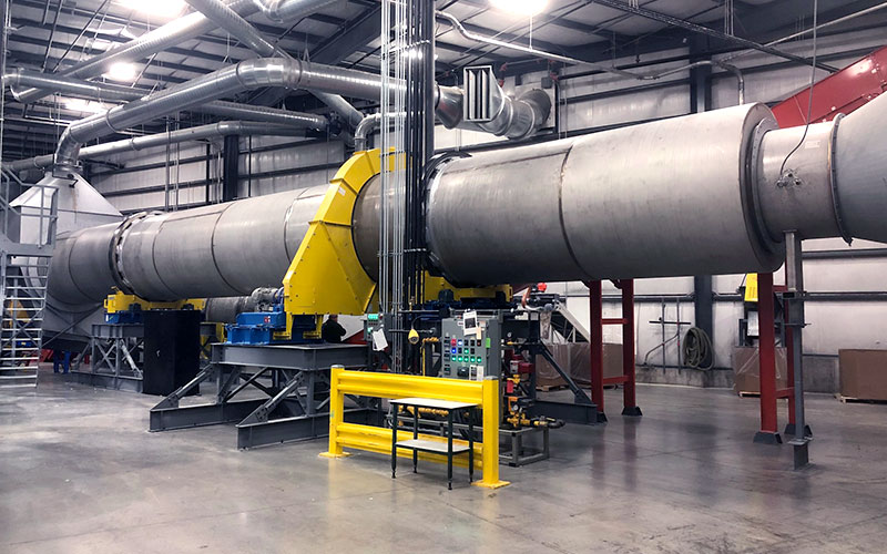
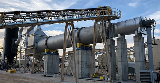
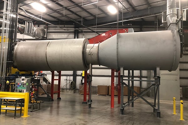
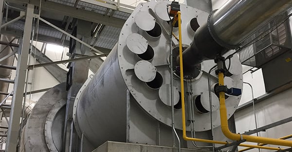
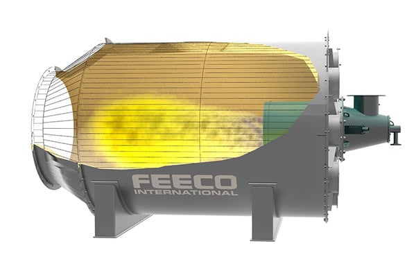
INDIRECT ROTARY DRUM DRYERS
Unlike direct dryers, indirect dryers do not rely on direct contact between the material and process gas to dry the material. Instead, the rotating drum is enclosed in a furnace, which is externally heated. Instead, contact with the externally heated drum shell dries the material.
While indirect dryers are less efficient compared to their direct counterparts, they offer some advantages that can make them an attractive alternative.
FEATURES
- Diameter: 3′ – 15′ (1 – 4.6m)
- Capacity: 1 TPH – 200 TPH (1 MTPH – 181 MTPH+)
- Specially designed lifting flights to maximize heat transfer between the material and hot gas stream
- Heavy-duty design and construction for many years of service
- Process and mechanical warranties
- Various drive assemblies available
Optional Components
- Knocking Systems
- Trommel Screen
- Liners
- Machined Bases
- Screw Conveyor Feeder
- Automatic Gear Lubrication System
- Exhaust Handling Equipment
- Various Burner Configurations
- Various Seal Options
- Ductwork
Material Options
- Carbon Steel
- Stainless Steel
- Specialty Alloys
- Explosion Bonded
- AR Steel
Accommodates Various Fuel Types
- Fuel Oil
- Natural Gas/Propane
- Electricity
- Waste Heat
- Biogas
INDIRECT DRUM DRYER COMPONENTS AND PARTS
The image below shows the standard components of an indirect rotary dryer. Click image to view larger.
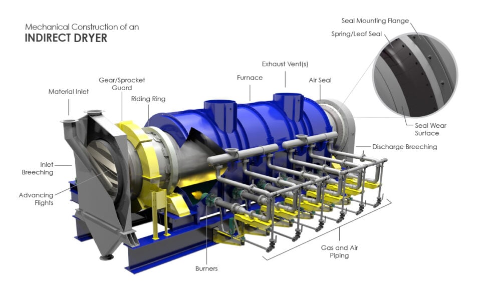
A – Material Inlet
B – Gear/Sprocket Guard
C – Riding Ring
D – Furnace
E – Exhaust Vent(s)
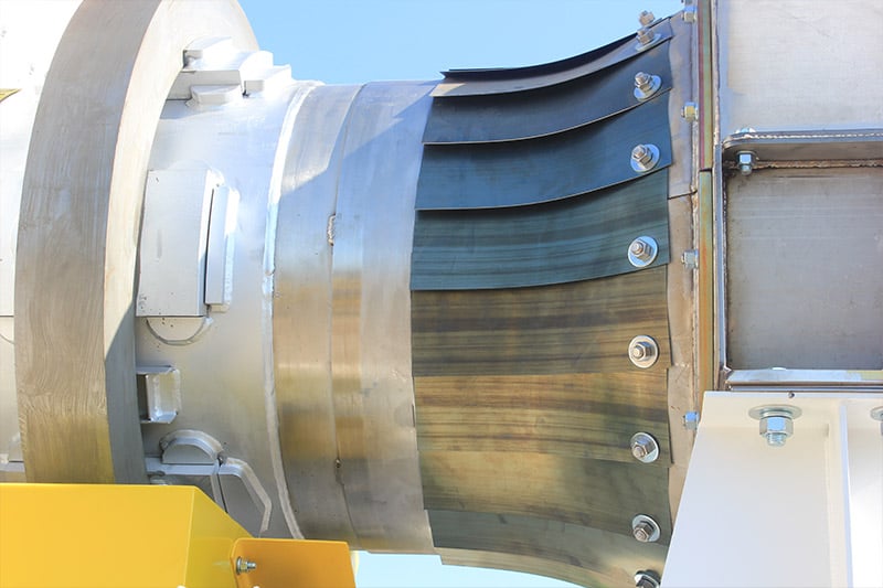
F – Air Seal
G – Spring/Leaf Seal
H – Seal Mounting Flange
I – Seal Wear Surface
J – Discharge Breeching
K – Gas and Air Piping
L – Burners
M – Advancing Flights
N – Inlet Breeching
RESOURCES
Rotary Drum Dryer ARTICLES
BROCHURES
Rotary Dryers & Coolers Brochure
Frac Sand Dryers Brochure


Rotary Dryer Frequently Asked Questions (FAQs)
A rotary dryer works by heating material, either directly or indirectly, using controlled temperatures and a predetermined retention time to remove moisture.
A rotary dryer consists of a large, rotating drum through which wet solids are passed. The mode of heating depends on whether the unit is of the direct or indirect configuration, with direct dryers being more common because of their higher efficiency. In direct dryers, material is passed either co-currently (same direction as combustion gases) or counter-currently (in opposition to combustion gases). Lifting flights cascade the material through the stream of combustion gases to promote maximum heat transfer between gas and solids.
In the indirect configuration, the rotating drum is sealed off from combustion gases and externally heated. Material is indirectly heated through contact with the drum shell.
The principle difference between a direct rotary drum dryer and an indirect one, is how heat is introduced to the material. Direct dryers rely on convective heat transfer from direct contact between the material being processed and the combustion gases to efficiently dry the material. Conversely, indirect dryers avoid contact between the material and combustion gases, instead relying on heat transfer to occur through the drum shell wall via conduction.
While this approach is less efficient than the direct dryer type, it is an essential processing option when working with materials that must be processed in an inert atmosphere, such as when processing sterile products. The indirect configuration is also chosen when processing ultra-fine materials, as it avoids the risk of solids becoming entrained in the gas flow and ending up in the exhaust gas system.
Rotary dryers can accept a variety of fuel types, including:
- Fuel oil
- Natural gas/Propane
- Waste heat
- Biogas
- Electricity
- Steam
The rotary dryer design process differs across manufacturers and depends on whether or not the manufacturer relies on standardized designs.
Since rotary dryers are best designed around the specifications of the given application and material to be processed, standardized designs, while less costly and requiring less production time, are inherently not as effective or efficient.
For a truly high-performance rotary dryer, the design process must take into account a wide range of factors such as inlet and outlet moisture, bulk density, heat transfer properties, material consistency and fragility, and more.
The rotary dryer manufacturer will gather the necessary data points and use computer dryer sizing calculations to determine the optimal drum size. Depending on the process goals and application, dryer feasibility testing may be necessary to assess the material’s behavior in the dryer and define the process data necessary for scale-up.
In addition to the process data, the dryer manufacturer will also consider material characteristics and process goals that will influence the design. This might mean selecting different materials of construction, assessing flight design, or adding customizations such as knocking systems or trommel screens.
Rotary dryers are capable of handling a wide range of throughput – typically anywhere from 1 TPH – 200 TPH. Rotary dryer capacity is a function of drum size and allowable air velocity.
Rotary dryer manufacturers will require the following information to design a rotary dryer:
- Desired throughput
- Inlet and outlet moisture
- Material bulk density
- Inlet and outlet temperature
- Maximum material temperature
- Specific heat
- Particle size (minimum, maximum, and average)
- Desired fuel source
- Higher heating value of fuel source
- Plant elevation
- Ambient air temperature at plant
- Special accommodations (is material explosive, abrasive, etc.)
Rotary dryers and kilns are similar in design, but are employed for different reasons. Rotary dryers remove moisture from the material, while rotary kilns are intended to cause a chemical reaction or physical change in the material. For this reason, rotary kilns are typically operated at higher temperatures than dryers, and therefore, are designed with a higher heat tolerance in mind.
Rotary dryers can be constructed from a wide range of materials, the choice of which is dependent on the temperatures employed and the characteristics of the material to be processed. Common materials of construction include:
- Carbon steel
- Stainless steel
- Specialty alloys
- Explosion bonded steel
- Abrasion-resistant (AR) steel
The dryer may also utilize multiple materials of construction to meet the needs of the material being processed as well. For example, the sticky nature of some materials may benefit from using polished stainless steel for the inlet section and carbon steel for the remainder of the drum shell. The polished stainless steel will discourage sticking near the inlet and give material a chance to dry a bit before it reaches the carbon steel, at which point the potential for sticking will be reduced.
Rotary dryers require a few pieces of support equipment. A complete dryer system consists of:
- Exhaust gas handling (or off-gas handling), where emissions are treated and any particulates are recovered. This includes scrubbers, cyclones, baghouses, electrostatic precipitators (ESP), and more.
- Induced Draft (ID) fan, which draws air through the system to create a negative pressure
- Burner, to produce the combustion reaction between the fuel source
- Dilution air fan to allow for better control of the on gases
- Combustion chamber (optional) to house the combustion reaction
- Control system to control the drying rate
- Material handling equipment, such as conveyors, to carry material to and away from the system
Rotary dryers typically operate at temperatures between 200°F and 2200°F (93 to 1200°C).
The choice between a rotary dryer and fluid bed dryer is a matter of capabilities. Rotary dryers are best suited for demanding drying applications, such as those found in the mining industry. They are also a better choice when variation in feedstock is common. Fluid bed dryers are more suited to lighter-duty applications. For more information, see Rotary Dryer or Fluid Bed Dryer.
Yes, rotary dryers are easily automated. Depending on the manufacturer, automation capabilities may differ. FEECO has partnered with Rockwell Automation to offer dryer automation capable of monitoring, collecting, and trending various data points such as current (amps), fan speed, feed rate, fuel usage, gas sampling & analysis, horsepower, system pressures, temperatures, and more.
Yes. In fact, FEECO recommends rotary dryers be customized for the application as much as possible, as this will produce the most efficient and reliable drying solution.
Several aspects of the rotary dryer can be customized, including materials of construction, flight design and pattern, sizing, support equipment, and more.