The FEECO website has recently seen new additions of exciting content: a 3D rotary kiln diagram and an interactive, 3D hammer mill model.
We’ve been producing 3D diagrams and models to give our customers a more thorough understanding of the equipment we manufacture, as well as the quality craftsmanship that goes into our products. Advanced technologies are a driving force at FEECO, and we will continue using the most innovative software programs to help our customers better envision their equipment designs and layout.
All of FEECO’s equipment is custom designed around each customer’s material and overall processing needs, and thus these diagrams and models provide a general overview only.
The rotary kiln diagram below is labeled with its standard components, in addition to the corresponding key. Click directly on the diagram to see a magnified version. Visit our hammer mill page to see the interactive, 3D hammer mill model.
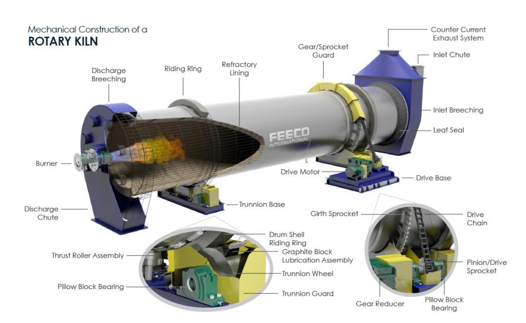
Mechanical Construction of a Rotary Kiln (3D Rotary Kiln by FEECO International)
| Rotary Kiln Components & Parts | |
| A – Discharge Breeching B – Riding Ring/Tire C – Refractory Lining D – Drive Gear Guard E – Counter Current Exhaust System F – Inlet Chute G – Inlet Breeching H – Leaf Seal I – Drive Base J – Drive Chain K – Pinion/Drive Sprocket L – Pillow Block Bearing | M – Gear Reducer N – Girth/Driven Sprocket O – Drive Motor P – Trunnion Base Q – Drum Shell Riding Ring R – Graphite Block Lubrication Assembly S – Trunnion Wheel T – Trunnion Guard U – Pillow Block Bearing V – Thrust Roller Assembly W – Discharge Chute X – Burner |